
|
|
|
||
|
|
|
||

This article provides overview of panelboard configuration with enhanced features with more than 100 improvement ideas from channel partners and sales to make panel takeoff more efficient.
- Global setting/defaults to speed up jobs with many panels
- Circuiting panel / Changing breaker placement is easier
- Placing breakers across kits in the P2 panel is a lot easier
- Easy to add multiple sections
- Implemented most voted channel feedback/ideas from the feedback tool to improve productivity and ease of use
1. Create a new quote or open an existing quote and click on the "Add Products" from action menu.
2. Then click on the "![]() " to launch the panelboard.
" to launch the panelboard.
.png)
3. On doing so, the following is available for the user.
.png)
4. Option available to the user to configure
|
# |
Keyboard Keys |
Action |
|
|
1 |
Tab Key |
To move to the next attribute for selection |
|
|
2 |
Shift + Tab Key |
To move to the previous attribute for selection |
|
|
3 |
Space key |
To check or uncheck the check box |
|
|
4 |
Down Arrow or Up Arrow Key |
Selection of value |
|
|
5 |
Shift + P Key |
To move to the panel tab |
|
|
6 |
Shift + S Key |
To move to the section / main tab |
|
|
7 |
Shift + L Key |
To move to the layout / design tab |
|
|
8 |
Shift + A Key |
To navigate to the general tab |
|
|
9 |
Shift + B Key |
To navigate to the interior tab |
|
|
10 |
Shift + C Key |
To navigate to the front and enclosure tab |
|
|
11 |
Shift + D Key |
To navigate to the nameplates tab |
|
|
12 |
Shift + E Key |
To navigate to the panel type tab |
|
|
13 |
Shift + F Key |
To navigate to the paint tab |
|
|
14 |
Shift + G Key |
To navigate to the product service tab |
|
|
15 |
Shift + I Key |
To navigate to the quantity attributes for entry |
|
|
16 |
Shift + H Key |
To navigate to the devices attributes for selection |
|
|
17 |
Shift + J Key |
To navigate to the amperage attributes for selection |
|
|
18 |
Shift + K Key |
To navigate to the pole attributes for selection |
|
|
19 |
Shift + M Key |
To navigate to the installation attributes for selection |
|
|
20 |
Shift + N Key |
To navigate to the accessories for selection |
|
|
21 |
Ctrl+ Enter |
To add breaker (to click "Add Branch") |
5. To have the default values sent to the attributes, we have the global setting/defaults to speed up the the configuration as shown below which can be enabled from the following option.
Click on the setting as shown below from the task menu. [![]() ]
]
.png)
On doing so the following is available to the user. Select the "Drawing Preferences" to set complex configurators.
.png)
Drawing preferences can be set the following products in COMPAS Go
|
# |
Products |
Attributes |
|
|
1 |
Switchboard |
|
|
|
2 |
Panelboard |
|
|
|
3 |
PowerMod |
|
|
|
4 |
Busway |
|
|
|
5 |
LVS-RCS-USS |
|
|
|
6 |
MCC |
|
|
|
7 |
MCC Unit Only |
|
After selecting the preferred attributes, click "Save" to have them applied to all the projects drawing generations. If user wants to view the drawing preference from a quote during drawing generation, it is possible. Also the settings can be modified. To do so, click on the action menu from the quote and select the report. On doing so, the following is available to the user to view or modify the drawing preference.
.png)
6. User can navigate to the "Section / Main" tab after click the tab (or use shortcut key Shift + S). Following is displayed to the user.
.png)
![]() - Used to create main and sections. Additional section is created with a single click.
- Used to create main and sections. Additional section is created with a single click.
![]() - Used to create branches or devices to the configuration.
- Used to create branches or devices to the configuration.
.png)
7. Action that can be performed by user
|
# |
ICON |
Action |
|
|
1 |
|
To configure the modification attributes |
|
|
2 |
|
Add main / section to the configuration. Simplified to create multiple section. |
|
|
3 |
|
Indicates the total poles for the section or device/branch |
|
|
4 |
|
Price of the device/branch or section |
|
|
5 |
|
View configuration |
|
|
6 |
|
Configure the breaker/branch or the section |
|
|
7 |
|
Delete the section or the breaker / branch |
|
|
8 |
|
Add branch device to the configuration |
|
|
9 |
|
Copy a device or branch |
|
|
10 |
|
Indicates the branch or device that is copied |
|
|
11 |
|
Duplicates the branch / breaker |
|
|
12 |
|
To clear all the copy actions |
|
|
13 |
|
Used to paste the branch / device that is copied |
8. After completing the configuration following is displayed to the user.
.png)
On completion of the configuration, the following information is available to the user.
|
# |
Information displayed |
Description |
|
|
1 |
|
Price for the completed configuration |
|
|
2 |
|
Size for the configured configuration used during commissioning |
|
|
3 |
|
Lead time for the configuration |
9. Click on the Layout / Design (or use shortcut key Shift + L). On doing so the default page is available to the user.
.png)
Clicking on the electrical view, the following is available to the user.
.png)
Clicking on the Manual Layout following is available to the user.
.png)
Actions that can be performed by the user.
|
# |
ICON |
Action |
|
|
1 |
|
Move device to workbench |
|
|
2 |
|
Move all the devices to workbench |
|
|
3 |
|
Refresh Layout |
|
|
4 |
|
To view workbench |
|
|
5 |
|
Refresh drawing |
|
|
6 |
|
View fill screen |
|
|
7 |
|
Select Kit to merge |
|
|
8 |
|
Move to workbench |
|
|
9 |
|
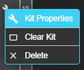
Configure the kit properties
|
|
|
10 |
|
To toggle between the sections |
|
|
11 |
|
Workbench to do manual placement |
Placing breakers across kits can be done by selecting the kits across sections. [ ![]() ]
]
.png)
Clicking on the drawing details tab as shown below is to add/view information for the following
- Nameplate Schedule
- Nameplate Details
- Circuit Schedule
- Circuit Schedule Detailed
- Abbreviations Electrical View
- Application Engineering Report
- Designations
- Notes Mechanical View
- Notes Electrical View
- Revision History
- Title
- Panelboard Components
.png)
Click on the drawing tab to view the engineering drawing for the configuration.
.png)
10. On completion, the panelboard configuration can be added to the quote. Select the following options to from action menu.
|
# |
Products |
Attributes |
|
|
1 |
|
|
|
|
2 |
|
|
|
|
3 |
|
|
|
|
4 |
|
|
|
|
5 |
|
|
|
|
6 |
|
|
|
|
7 |
|
|
|
|
8 |
|
|
|
|
9 |
|
|
|
|
10 |
|
|
|
|
11 |
|
|
