Switchboard: Overview
Siemens switchboards cover the entire spectrum of customer applications. Every aspect of Siemens switchboard design has been aimed at improving layout convenience, reducing installation costs and minimizing the impact and cost of system changes.
- Add devices in same order as electrical flow (incoming, main, branch)
- Complex ruleset (Layout rules) determines optimal sections required for the configured devices
- Available standard designs (if more than one layout available, then layout based on narrowest overall lineup)
- Available custom designs
- Layout rules create sections, working from incoming down, left to right
- Switchboard class (SB1, 2 & 3) is determined based on selected devices, accessories and layout
- Lead time based on class and options selected
- Pricing is usually updated twice per year: October 1st & April 1st
.png) .
.
Switchboard: Configuration .
|
COMPAS Go Configuration
|
Description of selection
|
|
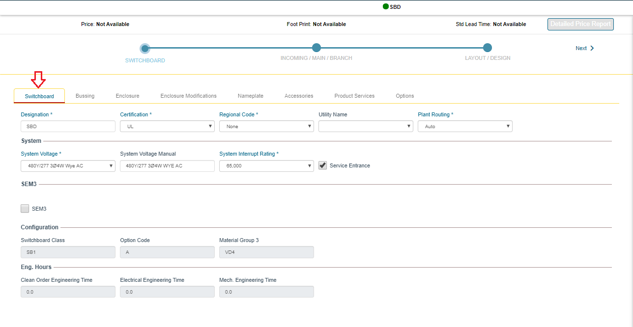
Switchboard
|
- Designation: Name of board
- Certification: UL is standard; cUL is optional. cUL is not the same as CSA!
- Regional Code: None is standard; EUSERC for West Coast; Chicago or NYC
- Utility Name: List is limited based on Regional Code Selection
- System Voltage: All standard voltages are listed – If not in list, add factory mod Most common voltage question is with DC systems… there are limited DC rated devices and 35k IR is max. 65k 500VDC devices do not exist.
- System Interrupt Rating: 10k to 200k (200k frames must be welded together in field)
- Service Entrance: If there is not a main device ahead of this board
- SEM3: Panel mounted 125-1200A devices will automatically have SEM3 when this is selected. (keep in mind that SEM3 CTs may increase section width)
|
|
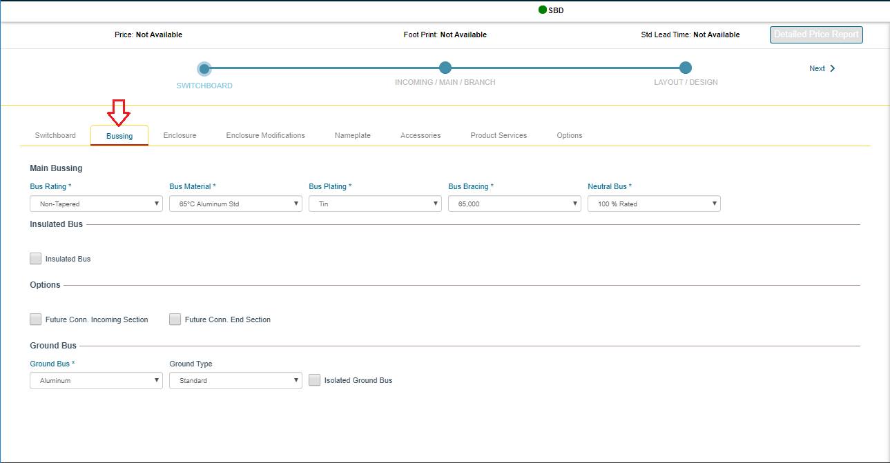
Bussing
|
- Bus Rating: Tapered – Thru bus amperage may be decreased by up to 2/3 of the supply; Non-Tapered – Thru bus will fully rated from supply to last section (this only applies to thru bus and not section bus)
- Bus Material: User selection, except when 5000A or 150/200k… these require 1000ASI CU
- Bus Plating: Use default, except for WWTP, which use Tin Plated CU (this adds 2+ weeks of lead time)
- Bus Bracing: Automatically selected based in system interrupt rating. (usually this is correct, but some specs may show higher bus bracing than interrupt)
- Neutral Bus: 100% is standard; 200% is optional (our maximum thru bus rating is 6000A, so cannot have more than 3000A main bus + 200% rated neutral bus… maximum distribution section bus is 4000A, so the max is 2000A main bus + 200% rated neutral bus)
- Insulated Bus: Tape wrapped bus – this is an uncommon option that adds 2+ weeks of lead time
- Future Conn. Incoming Section: – Forces system to add thru bus in the incoming section
- Future Conn. End Section: – In multi-section boards, this will force full width thru bus + fully rated bus
- Ground Bus: Defaults to match the main bus, but different material may be selected based on specifications
- Ground Type: Ground bus is automatically sized per UL E22578 Table 1, based in main amps, but you may force a specific size based on specifications
- Isolated Ground Bus: Standard ground bus is mounted directly to the frame; this option mounts on insulators to keep ground separate from frame
|
|
Enclosure
|
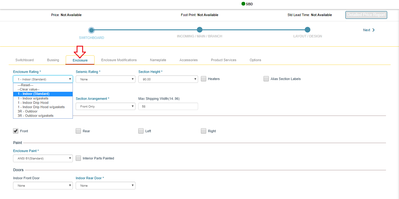
- Enclosure Rating:
- Seismic Rating: Ip = Importance Factor
OSHPD = California's Office of Statewide Health
Planning and Development Selections:
CBC\IBC 2015 Ip = 1.0 – The structure will survive a seismic event – This is for a typical commercial job.
CBC\IBC 2015 Ip = 1.5 – The equipment will be in working condition after a seismic event – This is typical for a hospital or critical power job.
OSHPD – Requirement for hospitals in California, where shake test required.
- Section Height: 90” is standard; 70” is custom
- Heaters: Usually used on outdoor boards to remove condensation before startup
- Alias Section Labels: Allows manual editing of section #. Used when add to existing, or customer wants different numbering scheme
- Alignment: Front & Rear – Standard; Rear – Optional
- Section Arrangement: Front Only – Standard
- Max Shipping Width: set this value when there are width restrictions in a room. Does not restrict section widths, but will prevent multiple sections from shipping together
- Access: Used on drawing to let plant/customer know where there will be access to the connections (usually only important in unusual conditions)
- Enclosure Paint: Standard is Grey, but plant can match most color samples
- Interior Parts Painted: Painted, rather than raw steel interior supports
- Indoor Front Door: 10” front extension (required to clear device handles) and full height front door over for section – Required when indoors with gaskets
- Indoor Rear Door: Full height rear door for each section
|
|
Enclosure Modification
|
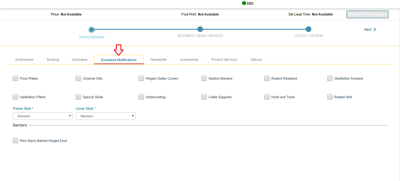
- Floor Plates: Steel plate in bottom of each section
- Channel Sills: Steel ‘U’ Channels to raise the section off of the floor
- Hinged Gutter Covers: Distribution panel side covers hinged to access the load cables easier
- Section Barriers: Steel & glastic vertical section barrier. Automatically added by code where needed; this option will add in all sections
- Rodent Resistant: Adds floor plates & screened vents to prevent rodent access
- Ventilation Screens: Mesh screens on vents
- Ventilation Filters: Filters behind vents
- Special Skids: Shipping skids, built per customer specifications
- Undercoating: Adds floor plates + protective coating to prevent rust on bottom
- Cable Supports: Channel supports for cables
- Hoist and Track: Track with hoist running across all sections, used on indoor sections only with draw-out WLs.
- Rubber Mat: Work mat in front of main section
- Frame Style: Frame gauge is automatically determined based on installed devices + ampacity, but this option specifies minimum gauge of frame structure
- Cover Style: Cover gauge is automatically determined based on installed devices + ampacity, but this option specifies minimum gauge of covers
- Plexiglass Rear Bus Barriers: Rear barrier will be plexiglass. Select rear bus barrier in section properties
- Plexi Barrs Behind Hinged Door: Optional custom barrier behind door mounted auxiliary devices
|
|
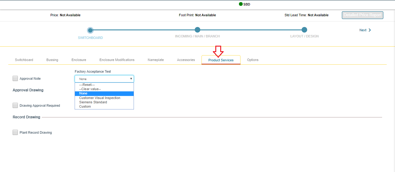
Product Services
|
Factory Acceptance Test:
- Customer Visual Inspection: Customer may visit the assembly plant and view the completed switchboard lineup
- Siemens Standard: Customer may visit the assembly plant and view the Siemens standard testing procedures (contact assembly location for details)
- Custom: Customer may specify testing or viewing requirements for plant visit
> Must attach document of custom specifications
> Application review will be required
> Application review step may add price for additional requirements
|
|
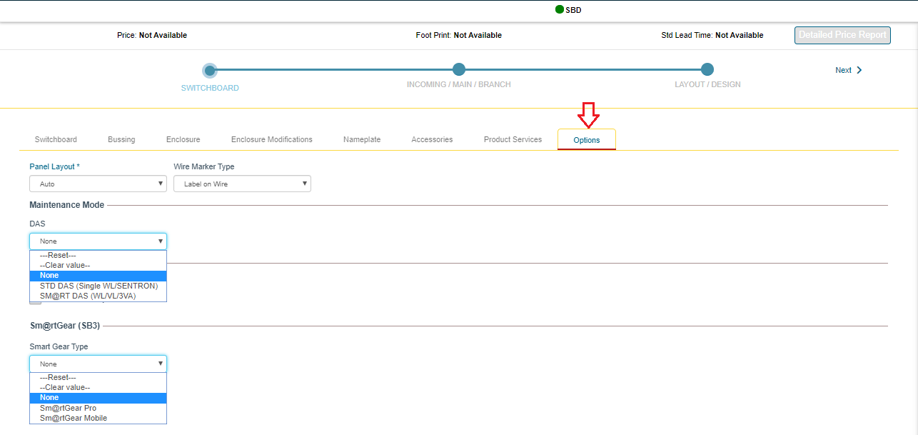
Options
|
- Panel Layout: Auto – Distribution section type will automatically be selected based on material and amperage, End-Feed – 3000A Max, distribution sections feed from top or bottom; Center-Feed – 4000A Max, distribution sections feed from the center of the riser bus
- DAS: click here for DAS
- Certified Test Reports: Test reports for each section (this is section only… not devices)
- Sm@rt Gear: click here for Sm@rt Gear
|
|
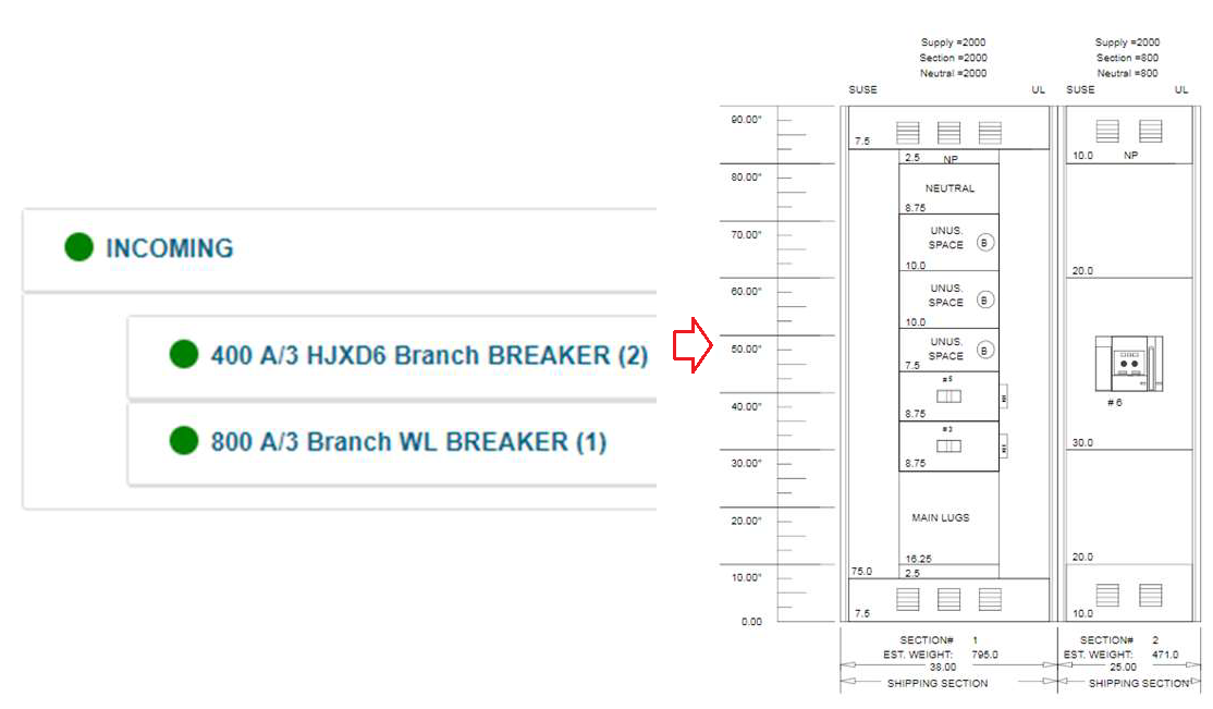
Switchboard: Incoming
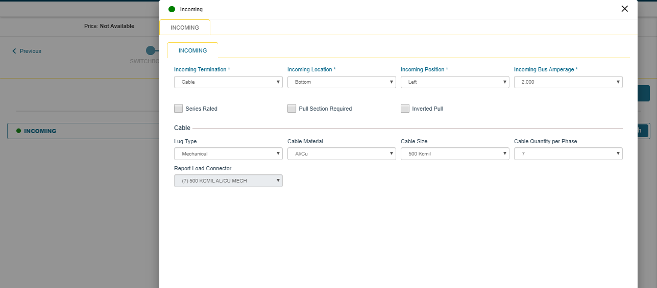
|
- Add one incoming for each supply to the lineup
- Incoming Types:
Cable – Need to know the size & qty of cable customer will use & review based on NEC table 310.15. Also, will it be entering top or bottom of section
Busway – Position & type are required. Coordinate with Spartanburg
Transformer – What type? Coordinate w/ MAP team
Bussplice to existing – Engineering will need existing job # or detailed drawings of existing
|
|
Main / Branch
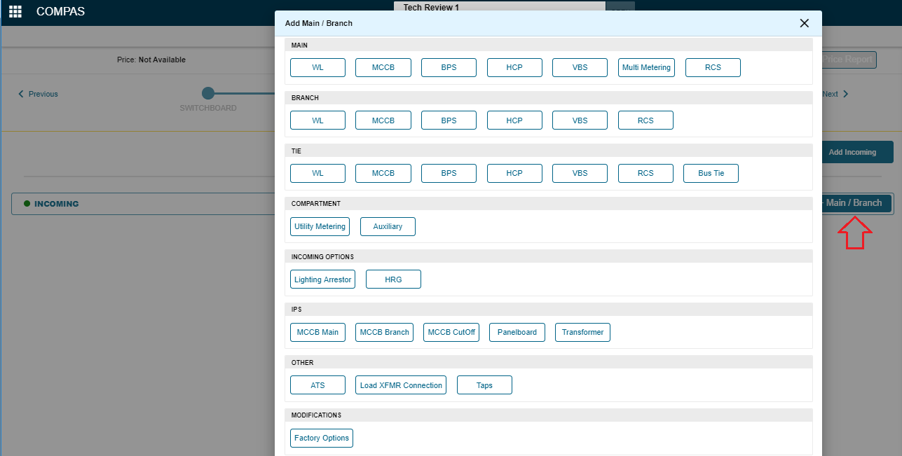
|
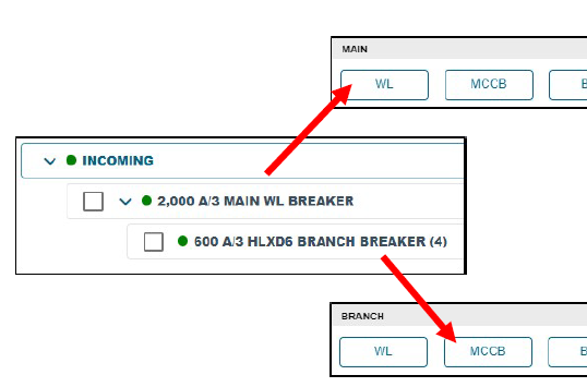
COMPAS defines a main relative the current switchboard lineup
|
|
Difference between Main and branch
.png)
|
COMPAS defines a main relative the current switchboard lineup
- If a device is feeding other devices in the same switchboard lineup, COMPAS defines it as a main
- If a device is feeding an external load (cable or busway), COMPAS defines it as a branch
|
|
MLO:
|
Configuration Steps:
- Add Incoming
- Add Branches from Main/Branch screen
- Click Layout/Design to view layout
Notes:
<2500A will not usually have a pull section added; select pull section required, at incoming level to force a pull section
>2500A will automatically have a pull section
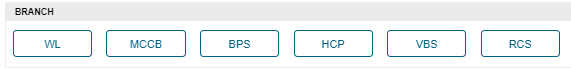
Make sure to add from the Branch list. All devices in a MLO feed external loads!
Is there a main ahead of this board? When service entrance is selected, max # of devices = 6
|
|
Single Main w/branches layout
|
Configuration Steps:
- Add Incoming
- Add Main from Main list
- Add Branches from Branch list
- Click Layout/Design to view layout
Make sure to add Main from the Main list
Make sure to add Branches from the Branch list
|
|
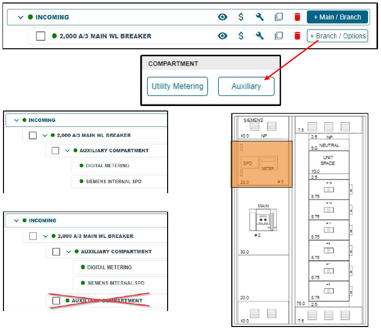
Individually Mounted Auxiliary Compartment
|
- Compartment mounting type defaults to the mounting type of the device that it is created below
- When created below any device where mounting = individual, compartment will default to individual
- Multiple components may be placed in a single Individually mounted auxiliary compartment
- Dependent on section width (38W compartment will hold more meters than a 20W compartment)
- 38W individual compartment can hold up to 9 PAC3200 meters
- Do not create multiple individual compartments below a single device. Sections may contain a maximum of one individually mounted compartment
|
|
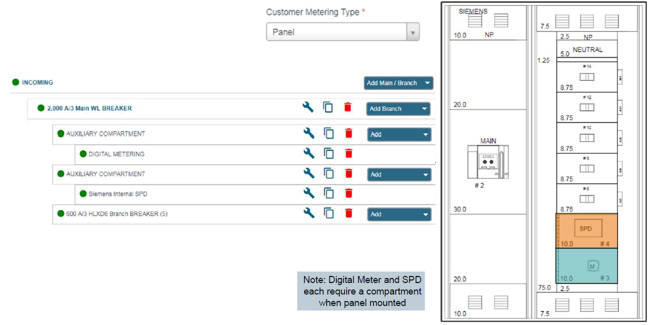
Panel Mounted Auxiliary Compartment
|
- Compartment mounting type defaults to the mounting type of the device that it is created below or can be manually set in the properties
- KB rules calculate compartment size based on devices
- If more devices are required than will fit into a single compartment, they must be added in another compartment.
|
|
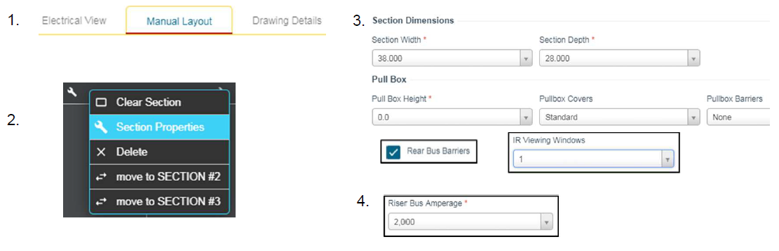
Navigation - Section Properties
|
Section Properties are accessed from the Manual Layout tab
- Choose Manual Layout View from the configuration tree
- Select wrench above section to modify and then choose Section Properties
- Update Width, Depth or add Pullbox, IR Viewing Windows or Rear Bus Barriers from the Section Tab
- Section Riser Bus may be modified on Distribution sections
|
.png)
- Standard DAS is for WL or Sentron only – If you select standard DAS and add a VL main, it will not have DAS
- DAS checkbox on breaker must be selected for that breaker to have DAS
- An auxiliary compartment is required for the controls on both types of DAS systems
- Individually mounted auxiliary compartment will hold DAS + Switch & Lights + Digital Meter + SPD
- WL can only support (1) auxiliary compartment; do not add two compartments – layout will fail
- Panel mounted aux compartment will fit DAS + Switch & Lights
- Panel mounted VL communications compartment will fit Switch & Lights + communication module(s), but not DAS System components
- If ‘Use Existing DAS’ compartment is selected, technical review will be required to verify compartment space
COMPAS Support
.
.png)
.png)
.png)


